
Announcements Information

[Optical Principles] Light Guide Design Case Study Information Title
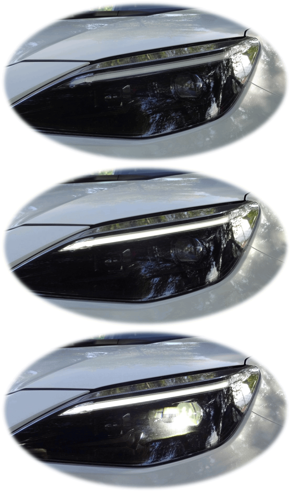
Light-guiding rods used as decorative elements in the headlamps of many cars.
What is the physical principle behind them?
This time, we will explain the optical principles that support the design of light-guiding rods, which are a type of light guide.
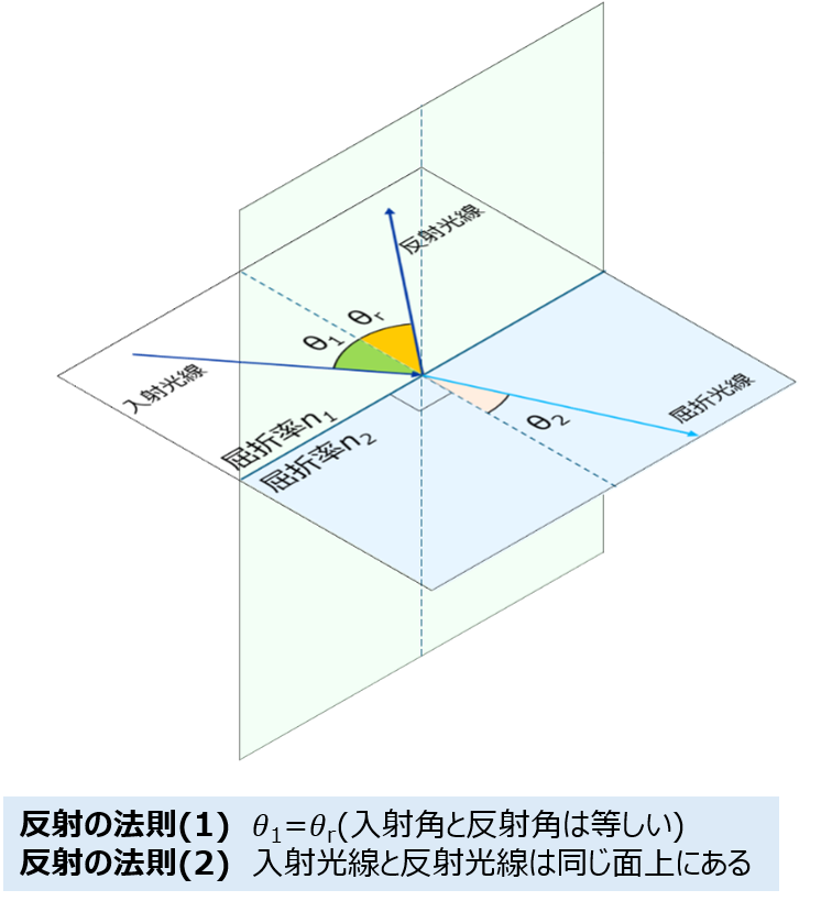
Snell's Law 1
1. Refraction
The phenomenon where the direction of light changes as it passes through the boundary between different substances.
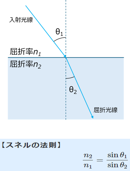
2. Law of Reflection
The phenomenon where the direction of light changes as it is reflected by the boundary between different substances.
Snell's Law 2
1. Refraction
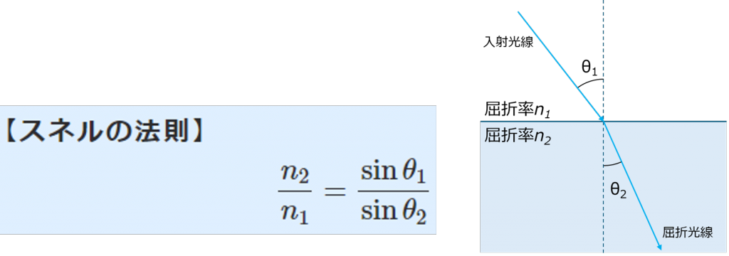
When light enters glass or resin from air (refractive index 1.00), it behaves as depicted in this image.
Of course, Snell's Law also applies in the reverse case, but refraction into air has certain limitations.
Total Internal Reflection 1
Total Internal Reflection and Critical Angle
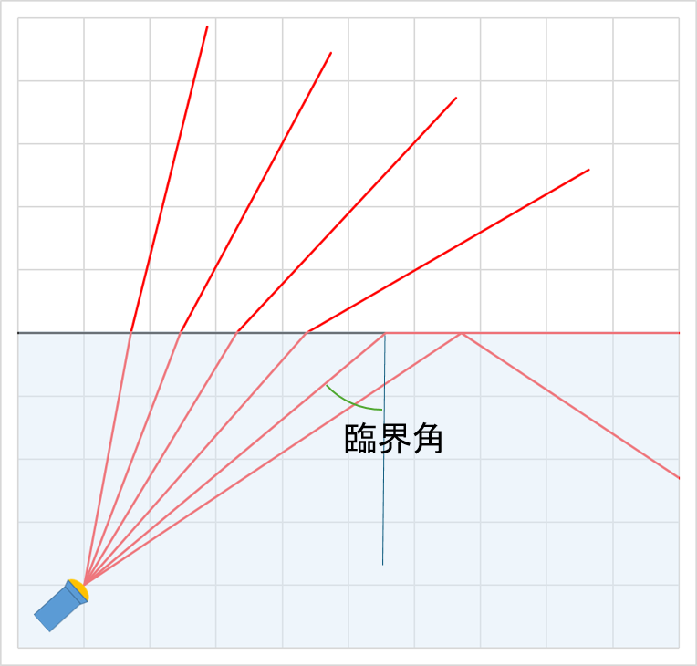
When light travels into air, as the angle of incidence increases, there comes a point where the angle of refraction reaches 90 degrees.
At this point, the light can no longer refract at a larger angle, so all light is reflected.
The angle of incidence at this time is called the critical angle.
Total Internal Reflection 2
Total Internal Reflection and Critical Angle
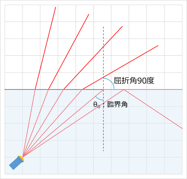
Let n0 be the refractive index of the medium of incidence and n1 be the refractive index of the destination medium. Snell's Law is n0sinθ0=n1sin90°
Rearranging this gives sinθ0=n1/n0
For example, when light travels from water to air, with n0=1.33 and n1=1.00, the calculation is sinθ0=1.00÷1.33≈0.752
θ0=48.753466631327≈49°
Looking up at the sky from the bottom of still water, it is possible to see the entire sky within a range of ±49°. Conversely, the water surface (internal reflection) beyond this range acts as a mirror with 100% reflectivity.
Total Internal Reflection 3
The Mechanism Behind Glowing Light Guides and Light Guide Plates
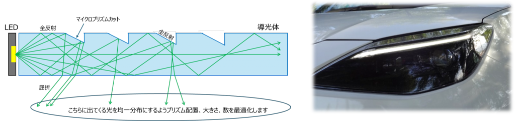
Light emitted from an LED source repeatedly undergoes total internal reflection at the inner surfaces of the light-guiding rod or plate, travelling towards the tip.
Partway along, micro-prism structures are created at locations where light is to be extracted (to make it appear lit from the outside). Here, the light is directed in the desired direction. The size, position (spacing), number, and angle of these micro-prisms are crucial parameters for achieving uniform illumination.
These optimised designs require tracing tens of millions to hundreds of millions of light rays from the light source. In the initial design phase, we will confirm the general behaviour of light by tracing rays on CAD (Computer Aided Design).
Light Guide Design Examples
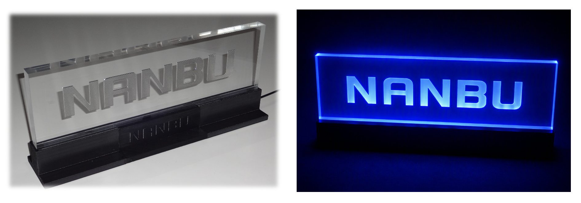
This light guide plate was manufactured in-house by fusing our core technologies: "Optical Design Technology" and "Micro-Cutting Technology."
Ray Tracing by Drawing
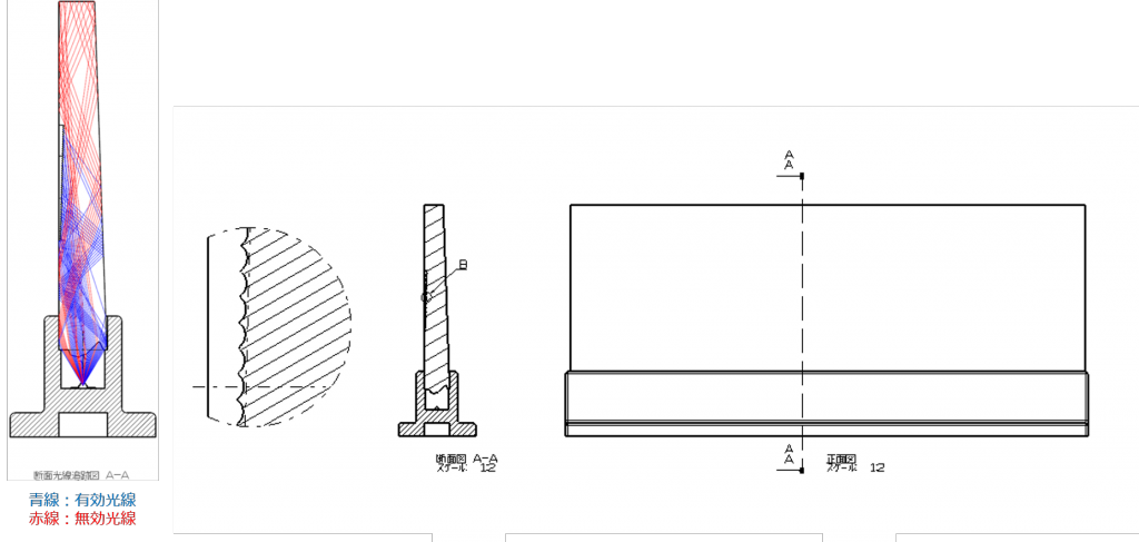
The external shape of the light guide is provisionally determined, and the light path from the light source (in this case, an LED) is drawn using CAD.
Using the law of refraction (Snell's Law), we examine the behaviour of light ray refraction and total internal reflection, and modify the light-introducing surface below the plate and the plate shape so that many light rays strike the logo surface.
In the diagram on the left, the light rays emitted from the light source are colour-coded into effective rays that reach the logo surface and ineffective rays that exit externally without reaching it.
Verification by Simulation
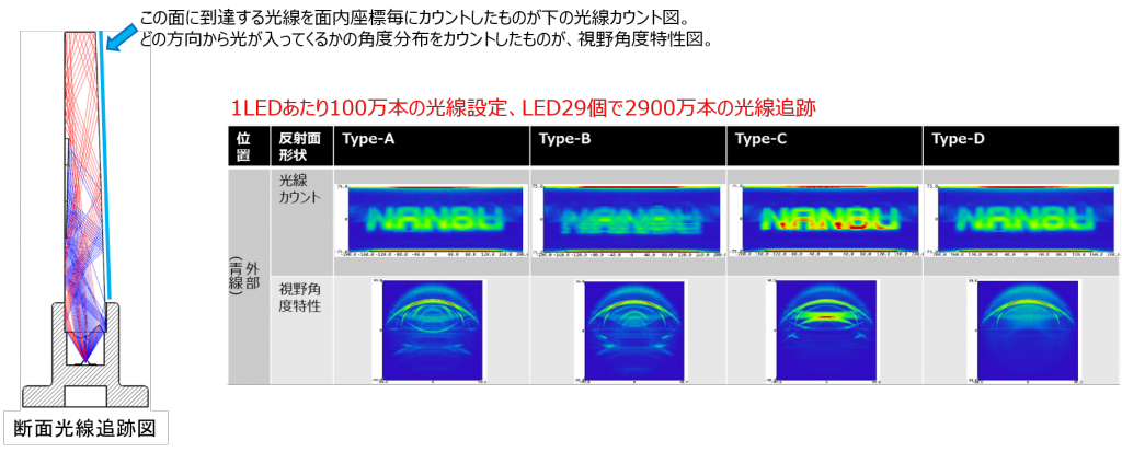
After provisionally determining the light guide shape through ray tracing by drawing, we perform illuminance simulations involving tracing a large number of light rays to verify how the logo surface lights up, whether it is visible from an angle, and the validity of the light guide plate shape, the light guide section (incident section) shape, and the reflective surface (scattering section) shape.
Once we confirm that the lighting is as per the design specifications as a result, we begin processing the optical surfaces.
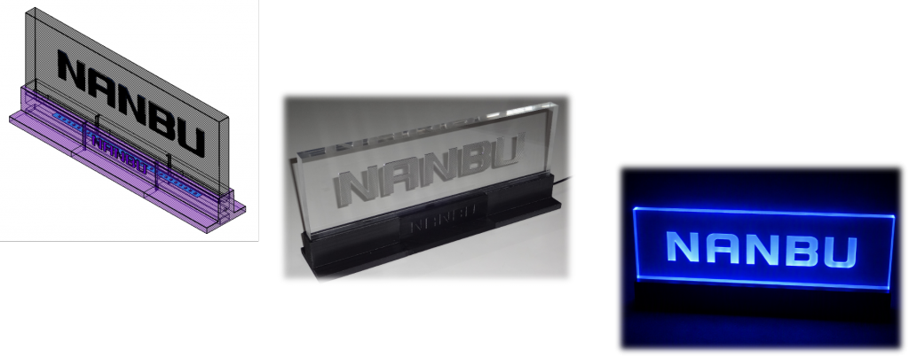
The lighting obtained through simulation has been reproduced in the actual product.
At Nambu Kasei, we utilise optical simulations in this manner to carry out everything from the design to the processing of various light guides.
・Related links within the site:
Technical Information | Optical Product Design & Manufacturing Technology
Technical Information | Mould Design, Manufacturing & Maintenance
Technical Information | Automotive Headlamp Optical Measurement (25m Dark Room)
Product Information | Inner Lenses & Light Guides for Automotive Lamps
Product Information | Microprism Arrays for Communication Lighting

